 Node
Node
A node that is attached to a component model functions a template for the connection point that Plant Modeller creates when a designer inserts an instance of the component in the 3D model.
Nodes are defined by:
-
Origin (the location of the node).
-
Direction (based on the normal of the connection face)
-
Face type
-
Nominal size
-
Rating
-
Direction (direction of width in rectangular node, symmetry axis of bolt holes in flanged node)
Inserting nodes
You can insert new nodes to a component model.
Prerequisites
-
(Optional) Parameters for type-specific properties. When Plant Modeller instantiates a component model to create a standard component or a pipe part, the face types of connection points are set as specified in the Catalog Part. However, nominal size and rating are as set in the node properties. So these should always be defined via parameters that pass this information from the associated Dimension Table to the component model.
Do the following:
-
On the Insert tab, in the Primitive group, click Node.
-
Click the point where you want to insert the new node. The Set Node Properties dialog opens.
-
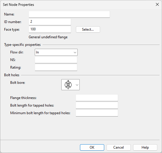
Set general node properties:
 Show/hide details
-
Name – Enter a name for the node. The name has to be unique in this GDL.
-
ID number – The ordinal number of the node. (This field is automatically populated.)
-
Face type – Click Select to select the face type from a menu. The contents of the menu is defined in the Codes and descriptions of connection faces configuration.
-
-
Set face type specific node properties:
Show/hide details
-
Flow dir – Select the flow direction: None, In, Out.
-
NS – Define the nominal size. You can parametrize it.
-
Rating – Define the rating. You can parametrize it.
Note: Flanged faces define the rating in the connection type, so you do not have to enter any value here.
-
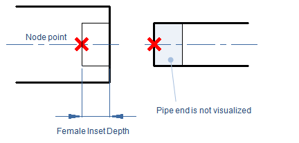
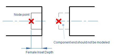
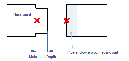
Inset depth – Inset depth enables proper visualization of female–male connections where one component is partly inside another component. You can parametrize it.
Show/hide details
-
Female component vs. pipe end – Inset depth allows Plant Modeller to hide the end part of a pipe that goes inside the female socket of a component. This makes it possible to use simpler 3D models that still produce correct visualization, instead of having to model the socket connection in such a way that the connecting pipe gets hidden.
-
Female component vs. male component – Inset depth does not affect this combination. The male component's connection point is modeled at the correct location, but the actual end of the component (which will be hidden by the female component) is not modeled at all.
-
Male component vs. pipe end – Inset depth allows Plant Modeller to hide the end part of a male component that goes inside a pipe. This is typically used for spiral duct parts. The parts look visually correct and do not cause collisions in collision detection.
Example: for a spiral duct outlet, we must define the second node so that the connected spiral pipe extends all the way to the white rim shown in this picture:
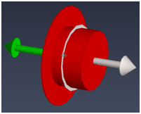
To prevent a collision in collision detection, we set inset depth to cover the distance that the connected pipe comes over the male connection.
In this example, we define inset depth by the expression "FullLength – Length", where the "FullLength" parameter measures the real length of the part from one end to the other and "Length" (which is the first parameter in the Dimension Table) defines the topological length between nodes 1 and 2.
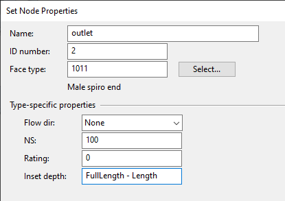
Note: A part that has its male connection defined in this way cannot be used with parts that have female connections. This is because the position of the parts comes from the connection point locations.
-
-
-
Set bolt hole properties for flanged faces:
Show/hide details
-
Bolt bore – Select how you want the bolt holes to be oriented in regard to the symmetry axis.

-
Flange thickness – If using automatic bolt length calculation and the bolt holes penetrate the flange, define the thickness of the flange here.
-
Bolt length for tapped holes – If using automatic bolt length calculation and the bolt holes are tapped (threaded), define the depth of the bolt holes here.
-
Minimum bolt length for tapped holes – If using automatic bolt length calculation and the bolt holes are tapped, you can define the minimum bolt length here. If this is zero, the program calculates the minimum length as 1.5 * bolt diameter.
-
-
Click OK.
Editing nodes
You can edit the properties of an existing node.
Do the following:
-
On the Component Modeller tab, in the Edit group, click Primitive.
-
Select the node and press Enter.
-
Right-click the view and select Edit Dims (Shift+O). The Set Node Properties dialog opens.
-
Edit the node properties as required, then click OK.
-
Press Enter or select Done from the context menu to accept the changes.